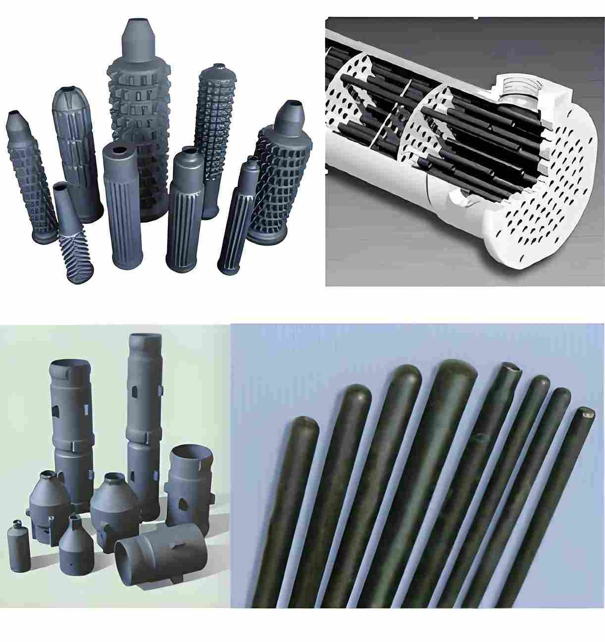
Designing silicon carbide (SiC) components is rarely a “one‑size‑fits‑all” exercise; engineers must balance extreme temperature tolerance, chemical resistance, and dimensional precision while keeping production lead‑times realistic. Below is the step‑by‑step framework we use at ZIRSEC to turn a raw concept into a reliable, export‑ready SiC part.
Quick Summary – FAQ
- What tolerances can you realistically achieve? Standard machining yields ±0.2 mm; tighter ±0.1 mm is possible with grinding or EDM.
- Which SiC grades are suitable for >1500 °C service? High‑purity (≥98 %) SiC with low residual free carbon is recommended.
- How long does a prototype take? 2–4 weeks for a CNC‑machined sample, 4–8 weeks for a full batch.
- What are the hidden costs? Tool wear, post‑machining inspection, and thermal shock testing add 15‑20 % to the bill of materials.
1. Define the Application Envelope
Every SiC part begins with a clear definition of the operating envelope. Ask yourself:
- Maximum continuous temperature? (Typical range: 1350 °C – 1600 °C for furnace tubes, 1200 °C for valve seats.)
- Thermal cycling profile? (Number of cycles, heating/cooling rate.)
- Chemical environment? (Oxidizing, reducing, molten salts, halogen gases.)
- Mechanical loads? (Compressive, tensile, bending, impact.)
Our recent project for a German pump‑valve maker illustrated the importance of this step. The client initially specified a 1400 °C steady state, but later revealed frequent rapid cooldowns, which forced us to tighten the thermal‑shock resistance specification and select a SiC grade with <0.1 % residual free carbon.
2. Choose the Right SiC Grade and Raw Material
SiC ceramics are available in several grades:
- Standard (≥98 % purity): Suitable for most high‑temperature heat‑exchange applications.
- High‑purity (≥99.5 %): Required for aggressive oxidizing atmospheres or semiconductor‑grade components.
- Reinforced (SiC‑fiber or SiC‑matrix composites): Used when flexural strength >150 MPa is essential.
We typically start with a standard grade and request a material test report (MSDS, COA) from the supplier. If the client’s specification calls for <1200 °C for a continuous period, the standard grade is sufficient; above that, we move to high‑purity.
3. Geometry – From CAD to Manufacturable Shape
SiC is brittle; sharp corners and deep internal cavities dramatically increase fracture risk. Follow these design heuristics:
- Keep wall thickness ≥2 mm for load‑bearing sections.
- Use fillets of at least 0.5 mm radius on all internal corners.
- Avoid sudden cross‑section changes; taper transitions over ≥5 mm.
- Limit aspect ratios (length/diameter) to <15:1 for tubes to prevent warpage during sintering.
For example, a custom SiC burner nozzle we delivered to a UK petrochemical client originally featured a 10 mm diameter inlet with a 2 mm wall. After three test runs, the nozzle cracked at the sharp inlet edge. By adding a 0.8 mm fillet and increasing the wall to 3 mm, the failure mode disappeared.
4. Tolerance Management
Machining SiC differs from metals. Tool wear is high, and the material’s hardness (≈9 Mohs) limits achievable tolerances.
| Process | Typical Tolerance | Surface Roughness (Ra) |
|---|---|---|
| CNC Milling (carbide tools) | ±0.2 mm | 3‑5 µm |
| Grinding (SiC abrasive) | ±0.1 mm | 0.8‑2 µm |
| EDM (wire) | ±0.05 mm | 1‑3 µm |
When a client requires ≤±0.05 mm, we usually recommend a two‑stage approach: rough CNC milling followed by precision grinding. This adds 10‑15 % to the machining cost but eliminates costly re‑work.
5. Prototyping Workflow
- Design Review: Our engineering team cross‑checks the CAD file for manufacturability, runs a finite‑element analysis (FEA) for thermal stress, and confirms material selection.
- Sample Production: For low‑volume (<20 pcs) we use rapid‑fire sintering on a pilot furnace. Larger batches go through our full‑scale 2 tonne sintering line.
- Post‑Processing: Grinding, polishing, and optional surface coating (e.g., Al₂O₃ sealant) to meet Ra specifications.
- Testing: Thermal‑shock test (heating to 1500 °C, then quench in air), flexural strength test, and dimensional inspection with CMM.
- Feedback Loop: Results are fed back to the CAD model; tolerances are adjusted, and the updated drawing is sent to the customer for approval.
Our standard lead‑time for a 10‑piece prototype is 3 weeks. For urgent orders we can compress it to 10 days by allocating dedicated furnace slots.
6. Scaling to Production
Once the prototype passes, we move to batch production. Key considerations include:
- Tool Life Management: SiC tools last 30‑40 hours on average; we schedule tool changes after each 50‑piece lot.
- Sintering Atmosphere: Argon or nitrogen purge prevents oxidation; for ultra‑high‑purity parts we use vacuum sintering.
- Quality Assurance: 100 % dimensional inspection for critical dimensions, 10 % destructive strength testing per batch.
In a recent partnership with a US turbine manufacturer, we delivered 5,000 SiC furnace tubes with a defect rate under 0.3 %—well below the industry benchmark of 1 %.
7. Documentation & Compliance
International buyers often request a full packet:
- Material Certificate of Analysis (COA)
- Material Safety Data Sheet (MSDS)
- 3‑D CAD files (STEP format)
- Inspection Report (CMM data, photos)
- Packaging & Shipping Declaration (Incoterms, HS code)
Our sales team bundles these into a single PDF that can be uploaded to the buyer’s ERP system, eliminating the need for repeated email exchanges.
8. Cost Drivers & Pricing Tips
Understanding where the budget goes helps you negotiate better:
- Raw Material: High‑purity SiC powder adds 30‑40 % to the base cost.
- Machining: Each mm of tolerance tightness incurs an extra $10‑$25 per part.
- Testing: Thermal‑shock and strength tests are billed at $150‑$300 per batch.
- Logistics: Export customs clearance for ceramic parts is smooth if documentation is complete; otherwise, expect delays of 3‑5 days.
For customers with recurring orders, we offer a volume discount tier: 5‑% off for 500‑pcs+, 12‑% off for 2,000‑pcs+, plus priority production slots.
9. Partnering with ZIRSEC – What We Bring
When you choose ZIRSEC, you gain:
- Direct access to a Chinese factory with 20 years of SiC experience.
- In‑house engineers who can co‑develop the part from concept to certification.
- 24‑hour inventory of standard sizes for immediate shipment.
- Custom‑order capability for low‑volume (<20 pcs) with rapid turnaround.
- Full supply‑chain support – order management, quality control, and door‑to‑door logistics.
Take a look at our Silicon Carbide Tubes page for a quick reference of dimensions, tolerances, and material grades we already stock.
10. Action Checklist
- Document the operating envelope (temp, chemistry, load).
- Select SiC grade – standard vs. high‑purity.
- Draft CAD with manufacturing heuristics (fillets, wall thickness).
- Set realistic tolerances based on chosen machining process.
- Submit drawing to ZIRSEC for a preliminary cost‑and‑lead‑time quote.
- Approve prototype specifications and testing plan.
- Review prototype results; iterate if needed.
- Confirm production batch size, tooling schedule, and delivery terms.
Following this checklist cuts the typical design‑to‑delivery cycle from 10‑12 weeks down to 6‑8 weeks for most industrial parts.
Designing silicon carbide components doesn’t have to be a guessing game. By aligning material science, precise geometry, and a disciplined production workflow, you can deliver parts that survive the harshest environments while keeping costs under control. If you’re ready to move from concept to a fully qualified SiC part, reach out to our engineering team at info@zirsec.com or request a free feasibility study through our website.